


Allion USA-SGS | Maroco Fan
In May 2019, the PCIe 5.0 specification was officially released by the PCI-SIG. The transfer speed became twice that of PCIe 4.0 at 32.0 GT/s. Throughput is also divided into x1, x2, x4, x8, x16 Lanes, so the maximum transmission capacity can reach 63 GB/s. PCIe plays an important role in consumer, server, or industrial applications.
The new transmission speed has undeniably become a technical threshold of connectors. In addition to the increase of transmission bandwidth, connectors are also becoming smaller and denser while being incorporated into a diverse range of applications. Servers are a major area of high-frequency applications, and in response to the new PCIe 5.0 era, connectors such as Gen-Z, MCIO and SAS are becoming increasingly important. This article will first introduce Gen-Z and MCIO, and the SAS part will be explained in the next article.
Gen-Z
The mechanism design refers to the specification of SFF-TA-1002. As shown in the figure below, it is divided into 4 connectors: 1C, 2C, 4C, 4C+. The PCIe Pinout design is based on the SFF-TA-1009 specification. The Gen Z transmission bandwidth ranges from 2.5 GT/s NRZ to 112 GT/s PAM-4, and this specification can also be applied to PCIe 6.0 in the future.
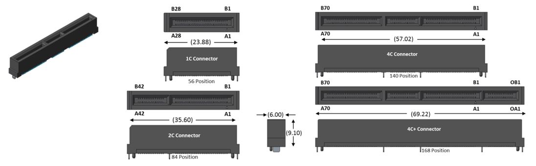
Image Source: SFF-TA-1002 Specification
There are four slot directions—straight, right angle, orthogonal, and straddle—as shown in the figure below. However, it should be noted that the transmission bandwidth of the orthogonal direction slot only supports up to 16 GT/s NRZ.
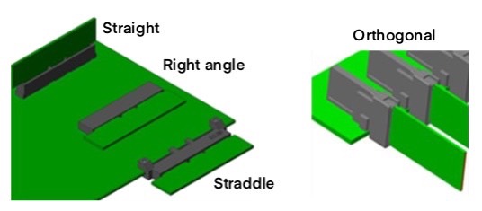
Image Source: SFF-TA-1002 Specification
Gen-Z Form Factor for Serve
- DESFF E1.S: It can replace M.2 and improve some of the shortcomings of M.2 in the past, such as: no hot swap, high temperature and over temperature. In addition, PCIe is expected to use up to 4 Lanes (Gen Z, 1C) in SSD applications, but according to the design conditions of the Form Factor of E1.S, if there are other application requirements, power can provide up to 20W, 8 Lanes (Gen Z , 2C).
- DESFF E3: Used to replace U.2. The lanes of PCIe range from 4 to 16 Lanes (Gen Z, 4C), and the Power can be up to 70W.
MCIO
MCIO is the abbreviation of Mini Cool Edge IO, and the mechanism design refers to the SFF-TA-1016 specification. It is divided into vertical and right angle. As shown in the figure below, the form factor is divided into 38-pin, 74-pin, 124-pin and 148-pin. Transmission bandwidth ranges from 25 GT/s NRZ to 112 GT/s PAM4. The same can be used by PCIe 6.0 in the future.
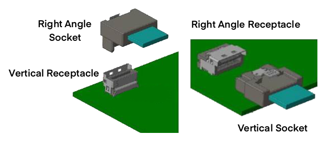
Image Source: SFF-TA-1016 Specification
MCIO uses the number of pins to classify the form factor rather than by lane, because the sideband in the definition of pinout can be used as a high-frequency signal flexibly. The form factor of 38-pin is used to illustrate: the originally defined high-frequency pin is only x4 Lanes, but after using the sideband as a high-frequency signal pin, it can be expanded to x6 Lanes, as shown in the figure below. In this way, PCIe x1, x2, x4, x8, x16 Lanes can all meet the requirements.
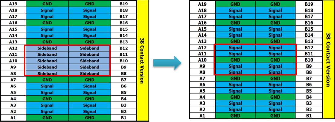
Image Source: SFF-TA-1016 Specification
The challenge of high-speed connectors
As mentioned above, while the transmission speed is increased, the pin size of the connector is reduced and the number of transmission channels (lanes) is also increased. Compared with the low-speed connector in the past, it is a relatively high technical threshold. The first major issue is the problem of bandwidth. Can it reach the expected speed of transmission? The quality of the bandwidth is determined by Insertion Loss (IL) and Return Loss (RL), which are directly and indirectly related to the material, thickness, and width of the metal.
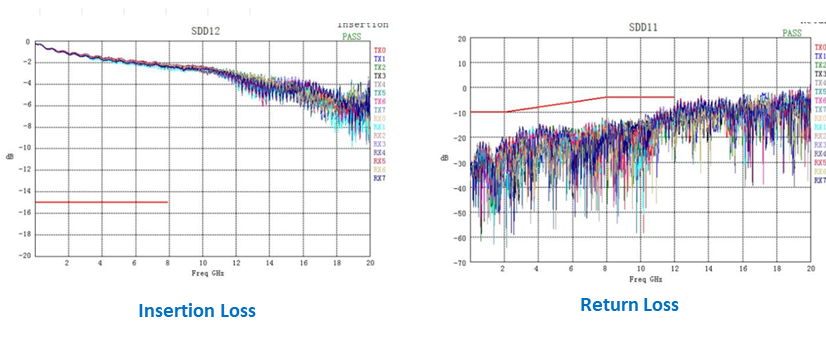
Ideally, the lower the IL and RL result the better, because the loss is minimal and the transmission data bandwidth can be increased.
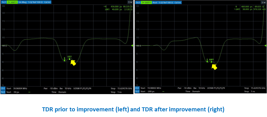
The second is the contact impedance1 when the plug is in contact with the Receptacle. When contact impedance is too poor and a higher frequency signal is encountered, a great return Loss will be generated, resulting in a decrease in the bandwidth.
1 not to be confused with contact resistance
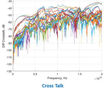
The third is Crosstalk. As mentioned before, the pin size is reduced and the number of lanes is increased, resulting in closer high-speed pins. These conditions will increase the impact of crosstalk. In addition, signal radiation that is too strong (for example, the return loss is too large) will also increase the crosstalk.
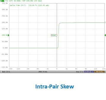
Finally, there is Skew. Skew is the time difference between the output signals when two identical signals enter the connector at the same time. At low frequencies, if the difference between the two signals is dozens of ps, errors are unlikely to occur; but at high frequencies, the time difference between 5 and 10 ps is very likely to cause errors. The skew between high-frequency pins and pins is called intra-pair skew, and the high-frequency pair-to-line (between pair and pair) is called inter-pair skew. Therefore, it is also a challenge to keep the signal error of each pin within the specification.
The above has introduced Gen Z and MCIO connector and the challenges facing high-speed signals. Allion is a cable and connector Authorized Test Center certified by various standards associations such as the USB-IF, HDMI Forum, and VESA. We have rich experience in testing cables and connectors for high-frequency signals. In addition, for related test fixtures, Allion can also customize the design and development according to customer needs, so that customers can obtain validation or certification results in the shortest time.
If you have cable and connector test needs, please feel free to contact us at: service@allion.com